
Pipe flanges are essential components of industrial piping systems. They are widely used in the oil and gas, petrochemical, chemical, power generation, and other process industries to connect pipes, valves, pumps, pressure vessels, heat exchangers, and other equipment.
Understanding different types of pipe flanges, their applications, dimensional standards, pressure classes, facing types, and associated components is important for piping engineers, designers, draftsmen, inspectors, and other professionals working in the oil and gas industry.
In this article, we will discuss different types of pipe flanges, their applications, applicable standards, pressure classes, facing arrangements, gaskets, bolting, and important considerations for flange selection.
1. What Is a Flange?
A flange is a mechanical piping component used to create a bolted connection between pipes, valves, pumps, pressure vessels, heat exchangers, and other equipment.
Flanges are widely used in the oil and gas, petrochemical, chemical, power generation, and other process industries.
A typical flanged connection consists of three main components:
- Two mating flanges.
- A gasket.
- Bolting (stud bolts and nuts).
These components work together to create a secure and pressure-tight connection.
One of the main advantages of using flanges is that they allow piping components to be easily dismantled for maintenance, inspection, cleaning, repair, and replacement.
Flanged connections are particularly useful in locations where regular maintenance or equipment removal may be required.
2. Main Functions of Flanges
The main functions of flanges in piping systems are:
- To connect two pipes or piping components.
- To connect pipes with valves, pumps, vessels, and other equipment.
- To provide detachable connections for maintenance and inspection.
- To facilitate the installation and removal of piping equipment.
- To provide pressure-tight connections when properly assembled with compatible gaskets and bolting.
- To close the end of a pipeline or equipment nozzle using a blind flange.
3. Types of Pipe Flanges
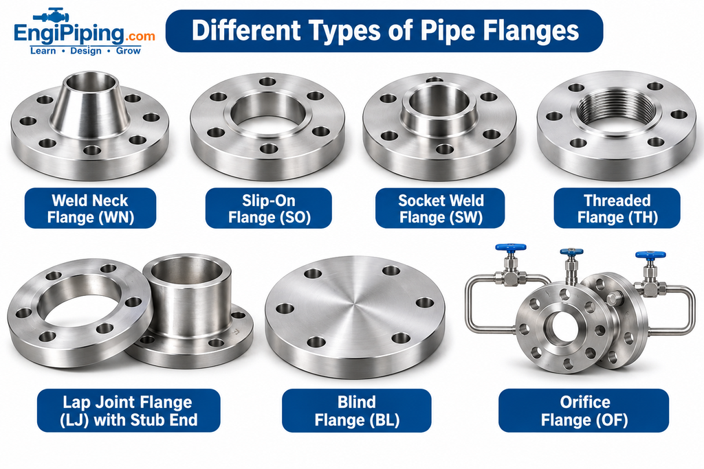
Different types of flanges are used in piping systems depending on design requirements, pressure, temperature, material, piping arrangement, and service conditions.
The most commonly used pipe flange types in the oil and gas industry are explained below.
3.1 Weld Neck Flange (WN)
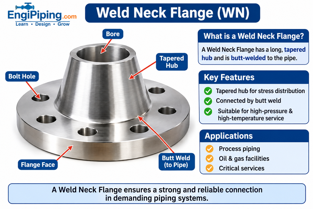
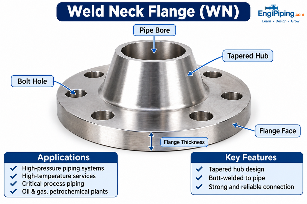
A Weld Neck Flange has a long, tapered hub that gradually transitions from the flange thickness to the pipe wall thickness.
It is connected to the pipe by a butt weld. The tapered hub helps distribute mechanical stresses between the flange and the pipe.
Applications:
- High-pressure piping systems.
- High-temperature services.
- Critical process piping.
- Oil and gas transmission and processing facilities.
- Piping systems subjected to fluctuating temperatures and mechanical loads.
Key Features:
- Connected to the pipe by butt welding.
- Suitable for demanding piping services.
- Available in different pressure classes and materials.
- Provides a gradual transition between the flange and pipe.
3.2 Slip-On Flange (SO)
A Slip-On Flange is designed to slide over the outside diameter of a pipe.
It is generally connected using fillet welds at the hub side and the flange side, as specified by the applicable piping code and design requirements.
Applications:
- General process piping.
- Low-to-moderate pressure applications where permitted.
- Utility piping systems.
- Small and medium-sized piping arrangements.
Key Features:
- Easy to position on the pipe.
- Requires fillet welding.
- Generally easier to install than a Weld Neck Flange.
- Requires proper welding as per applicable requirements.
3.3 Socket Weld Flange (SW)
A Socket Weld Flange contains a recessed socket into which the pipe is inserted before welding.
The pipe is inserted into the socket, positioned with the specified clearance, and connected using a fillet weld around the outside of the pipe.
Applications:
- Small-bore piping systems.
- Selected high-pressure piping applications.
- Instrumentation and utility connections.
- Piping systems where socket-weld construction is permitted.
Key Features:
- Suitable for smaller pipe sizes.
- Provides a compact connection.
- Requires fillet welding.
- Commonly used in small-bore piping systems.
3.4 Threaded Flange (TH)
A Threaded Flange has internal threads that match the external threads of the pipe.
It is connected by screwing the threaded pipe into the flange, eliminating the requirement for welding at the flange-to-pipe connection.
Applications:
- Low-pressure piping systems.
- Utility services.
- Selected hazardous-area applications where welding is restricted.
- Piping systems where threaded connections are permitted.
Key Features:
- No welding is required for the flange-to-pipe connection.
- Easy to install and dismantle.
- Requires proper thread compatibility.
- Suitable only where threaded connections are permitted by the design.
3.5 Lap Joint Flange (LJ)
A Lap Joint Flange is used together with a compatible stub end.
The flange is not directly welded to the pipe. Instead, the stub end is butt-welded to the pipe, and the Lap Joint Flange is placed behind its flared end.
One major advantage is that the flange can rotate freely around the stub end, making bolt-hole alignment easier during installation.
Applications:
- Piping systems requiring frequent dismantling.
- Systems where bolt-hole alignment is difficult.
- Selected corrosive services when used with suitable stub-end materials.
- Piping systems where lap-joint construction is permitted.
Key Features:
- Requires a compatible stub end.
- Allows flange rotation.
- Makes bolt-hole alignment easier.
- Can be economical when expensive corrosion-resistant stub-end materials are used with suitable backing flanges.
3.6 Blind Flange (BL)
A Blind Flange is a solid flange without a central bore. It is used to close the end of a pipeline, pressure vessel nozzle, or other flanged opening.
It can be installed or removed when access to the piping system is required.
Applications:
- Closing pipeline ends.
- Isolating equipment nozzles.
- Temporary or permanent pipeline termination.
- Pressure testing and maintenance arrangements, subject to approved design requirements.
Key Features:
- Does not have a pipe bore.
- Used to close flanged openings.
- Can be removed when access is required.
- Must be designed for the applicable pressure and temperature conditions.
3.7 Orifice Flange (OF)
An Orifice Flange is a specially designed flange assembly used with an orifice plate for measuring fluid flow in a pipeline.
It generally includes pressure-tapping connections that allow differential pressure to be measured across the orifice plate.
The differential pressure is used to calculate the flow rate through the pipeline.
Applications:
- Flow measurement systems.
- Oil and gas processing plants.
- Gas transmission pipelines.
- Process measurement and instrumentation systems.
Key Features:
- Designed for use with an orifice plate.
- Includes pressure-tapping connections.
- Used for differential pressure measurement.
- Manufactured in accordance with ASME B16.36 within its scope.
4. Other Special Types of Flanges
Apart from the commonly used flange types, several special flange arrangements are also used in piping and equipment connections.
4.1 Reducing Flange
A Reducing Flange is designed to connect piping components of different nominal sizes.
It provides a transition between different pipe or equipment connection sizes.
Application:
Used where a flange connection between different nominal sizes is required, subject to applicable design and dimensional requirements.
4.2 Long Weld Neck Flange (LWN)
A Long Weld Neck Flange has an extended neck and is commonly used in pressure vessel and equipment applications.
It is designed to provide an integral connection with the vessel or equipment, depending on the design.
Applications:
- Pressure vessels.
- Columns and towers.
- Heat exchangers.
- Other equipment connections.
4.3 Spectacle Blind Flange
A Spectacle Blind consists of two connected components:
- A solid plate (blind).
- An open spacer (spade or spacer section).
It is installed between two flanges and can be rotated to either block or allow flow through the pipeline.
Application:
Used for positive mechanical isolation during maintenance and shutdown activities.
4.4 Paddle Blind (Line Blind)
A Paddle Blind is a solid metal plate installed between flanges to provide positive isolation of a pipeline.
It is commonly used during maintenance, inspection, and shutdown activities.
Application:
Used where positive mechanical isolation of a piping system is required according to the approved isolation procedure.
5. Flange Dimensional Standards
In the oil and gas industry, flange dimensions, pressure ratings, materials, and manufacturing requirements are governed by applicable international standards.
The following ASME standards are commonly referenced.
5.1 ASME B16.5 – Pipe Flanges and Flanged Fittings
Covers pressure-temperature ratings, dimensions, tolerances, materials, marking, and testing requirements for pipe flanges and flanged fittings within its specified size and pressure-class scope.
5.2 ASME B16.47 – Large Diameter Steel Flanges
Covers large-diameter steel flanges in NPS 26 through NPS 60 within its specified scope.
It includes Series A and Series B flange dimensions and requirements.
5.3 ASME B16.36 – Orifice Flanges
Covers orifice flanges used in conjunction with orifice plates for flow measurement applications.
5.4 ASME B16.20 – Metallic Gaskets for Pipe Flanges
Covers metallic gaskets, including:
- Spiral-wound gaskets.
- Ring-type joint (RTJ) gaskets.
- Metal-jacketed gaskets.
5.5 ASME B16.21 – Nonmetallic Flat Gaskets for Pipe Flanges
Covers nonmetallic flat gaskets used in flanged connections within its scope.
Important: Always verify the applicable standard, pressure class, material specification, flange facing, gasket type, bolting, and design conditions before selecting a flange.
6. Flange Pressure Classes
Flanges are manufactured in different pressure classes depending on their design requirements.
Common ASME flange pressure classes include:
| Sr. No. | Pressure Class |
| 1 | Class 150 |
| 2 | Class 300 |
| 3 | Class 400 |
| 4 | Class 600 |
| 5 | Class 900 |
| 6 | Class 1500 |
| 7 | Class 2500 |
These pressure classes are not direct pressure values in PSI.
The allowable working pressure depends on several factors, including:
- Flange material.
- Operating temperature.
- Applicable pressure-temperature rating tables.
- Relevant design requirements.
Example:
A Class 300 flange does not mean that it can withstand exactly 300 PSI under all operating conditions.
The allowable pressure must always be determined from the applicable pressure-temperature rating tables.
7. Flange Facing Types
Flange facing refers to the surface configuration of the flange where the gasket is installed.
The main types of flange facings used in the oil and gas industry are explained below.
7.1 Raised Face (RF)
A Raised Face Flange has a slightly elevated sealing surface around the bore.
It is one of the most commonly used flange facings in process piping systems.
Applications:
Commonly used in:
- Oil and gas facilities.
- Petrochemical plants.
- Refineries.
- General industrial piping systems.
7.2 Flat Face (FF)
A Flat Face Flange has a completely flat gasket-contact surface extending across the flange face.
It is commonly used in selected low-pressure services and equipment connections, particularly where flat-face mating is required.
Applications:
- Selected low-pressure piping systems.
- Equipment connections requiring flat-face flanges.
- Connections where flat-face mating is specified.
7.3 Ring-Type Joint (RTJ)
A Ring-Type Joint Flange has a specially machined groove designed to accommodate a metallic ring gasket.
The metallic ring gasket provides sealing through controlled contact between the ring and the flange grooves.
Applications:
- High-pressure services.
- High-temperature services.
- Critical oil and gas piping systems.
- Selected refinery and petrochemical applications.
8. Pipe Flanges, Gaskets, and Bolting: Related Connection Components
Flanges, gaskets, stud bolts, and nuts work together to create a complete bolted piping connection.
Although gaskets and bolting are not classified as pipe fittings, they are essential components of a flanged connection.
8.1 Gaskets
A gasket is a sealing component installed between two mating flange faces to prevent leakage of the process fluid.
When the flange connection is tightened, the gasket is compressed to create a seal.
Common Types of Gaskets:
- Spiral-Wound Gasket.
- Sheet Gasket.
- Ring-Type Joint (RTJ) Gasket.
- Metal-Jacketed Gasket.
- Compressed Non-Asbestos Fibre (CNAF) Gasket.
Gasket Selection Criteria:
Gaskets are selected according to:
- Operating pressure.
- Operating temperature.
- Fluid or chemical compatibility.
- Flange facing type.
- Applicable design standards.
8.2 Stud Bolts and Nuts
Stud bolts and nuts are used to assemble two mating flanges.
They provide the required clamping force to compress the gasket and maintain a pressure-tight connection.
Main Components:
- Stud bolts.
- Heavy hex nuts.
Applications:
Used in flanged connections throughout oil and gas plants, refineries, petrochemical plants, and other industrial facilities.
The bolting material, dimensions, and tightening requirements must comply with the applicable piping specification and engineering requirements.
8.3 Flange Facing and Gasket Compatibility
The flange facing and gasket must be selected as a compatible combination.
Common arrangements include:
| Flange Facing | Suitable Gasket Arrangement |
| Raised Face (RF) | Suitable raised-face gasket |
| Flat Face (FF) | Suitable full-face gasket |
| Ring-Type Joint (RTJ) | Compatible metallic ring gasket |
Incorrect gasket selection or incompatible flange facings can result in leakage or damage to the connection.
9. Important Points to Consider When Selecting Flanges
Before selecting a flange for any piping system, the following parameters must be considered:
1. Pipe Size: The flange size must match the required nominal pipe size and connection arrangement.
2. Pressure Class: Select the appropriate pressure class based on the design conditions and applicable pressure-temperature ratings.
3. Material: Flange material must be compatible with the piping material and process fluid.
4. Temperature: Consider the minimum and maximum operating temperatures.
5. Flange Facing: Select RF, FF, or RTJ according to the design and mating connection.
6. Gasket: Ensure the gasket is compatible with the flange facing and process conditions.
7. Bolting: Select suitable stud bolts and nuts according to the piping specification.
8. Applicable Standards: Verify the relevant ASME, ASTM, MSS, or project-specific requirements.
9. Corrosion Requirements: Consider corrosion resistance and material compatibility.
10. Design Code: Ensure the flange selection complies with the applicable piping or equipment design code.
10. Conclusion
Flanges are essential components of piping systems in the oil and gas industry. They provide strong, detachable, and pressure-tight connections between pipes, valves, pumps, pressure vessels, and other equipment.
Different flange types, such as Weld Neck, Slip-On, Socket Weld, Threaded, Lap Joint, Blind, and Orifice Flanges, are selected according to the specific requirements of the piping system.
Understanding flange types, pressure classes, facing arrangements, dimensional standards, gaskets, and bolting is important for piping engineers, designers, draftsmen, inspectors, and other professionals working in the oil and gas industry.
A proper understanding of flanges helps ensure safe installation, reliable operation, and easier maintenance of industrial piping systems.
Learn More About Piping Engineering
Are you interested in learning more about piping engineering and the oil and gas industry?
Visit EngiPiping.com for more educational articles, technical information, practical examples, and learning resources related to piping engineering.
EngiPiping.com – Your Learning Resource for Piping Engineering.